For trackers, connect the ground wire (black with white stripe) first to the OBD2 port, four slots above the power connection. Then attach the orange power wire to the bottom right corner of the connector. Secure all connections with solder and insulate them properly. Route wires neatly behind panels and secure with zip ties to prevent interference. Position any antennas upright for ideal signal reception. The right wiring sequence guarantees your tracker functions reliably and accurately.
Understanding Barn Door Tracker Components
Enthusiasts venturing into astrophotography quickly discover the importance of a well-built barn door tracker. At its core, this device consists of three essential parts: a sturdy base plate, a precise pivot point, and an adjustable arm that holds your camera.
You’ll need to make sure the tracker properly aligns with the North Star for accurate celestial tracking. The heart of the system is a clock motor that drives the gear mechanism, rotating the arm at the sidereal rate of 15 degrees per hour to match Earth’s rotation.
When assembling your tracker, proper balance is vital. Position your camera carefully on the arm to prevent unnecessary strain on the motor and eliminate vibrations.
Always mount the entire setup on a robust tripod for stability during those long exposure shots.
Essential Wiring Tools and Materials
When assembling your barn door tracker, having the right wiring tools and materials will make the difference between frustration and success.
Start with quality wire strippers to remove insulation without damaging the wires underneath. You’ll need a soldering iron to create strong, reliable connections that won’t fail during operation.
Keep track of wire colors—black with white stripe typically indicates ground, while orange often signifies power. Secure your wiring with zip ties for a neat, organized layout that prevents tangling or disconnection.
Don’t forget heat shrink tubing to protect soldered joints from moisture and wear. Use double-sided tape for mounting components securely to your tracker.
Finally, a multimeter is essential for testing connections, ensuring proper voltage, and verifying continuity throughout your wiring setup.
Motor Selection and Technical Requirements

You’ll need to balance your tracker’s power requirements against the torque capabilities of potential motors, ensuring sufficient strength without excessive battery drain.
When analyzing speed compatibility, verify that your motor’s voltage specifications align with your power source while delivering the rotation rate necessary for smooth tracking operations.
Consider the motor’s physical dimensions carefully, as its form factor must fit within your tracker’s housing while allowing adequate space for heat dissipation and connecting wires.
Power Vs Torque Needs
Selecting the right motor for your tracker requires understanding the critical balance between power and torque requirements.
Power, measured in watts or horsepower, determines how much overall energy your motor can provide based on your tracker’s weight and desired speed.
Torque, measured in Newton-meters or foot-pounds, is essential for acceleration and hill climbing. You’ll need higher torque for trackers that require quick starts or operate on rugged terrain.
For ideal performance, you should match your motor’s specifications with your tracker’s load requirements, ensuring the continuous power rating exceeds maximum expected operational loads.
Consider brushless DC motors for your tracker—they typically deliver higher torque at lower power consumption compared to traditional brushed motors, resulting in improved performance and longer battery life for your tracking system.
Speed/Voltage Compatibility Analysis
As you integrate motors into your tracking system, proper speed and voltage compatibility becomes essential for ideal performance.
You’ll need to select motors that operate within the 5V to 12V range to match your OBD2 connector’s power output capabilities. Your motor should deliver at least 3000 RPM to guarantee accurate data transmission in tracking applications.
Don’t choose motors rated for voltages higher than your OBD2 power supply provides—this mismatch can cause overheating and device failure.
Keep the current draw under 2A to protect your vehicle’s electrical system from overload. Additionally, verify that your motor’s operational frequency aligns with your tracking system’s data acquisition rate.
This synchronization guarantees continuous, reliable tracking performance without data gaps or transmission errors.
Form Factor Considerations
The ideal tracker motor must fit seamlessly within your device’s compact housing while delivering sufficient power for reliable operation.
When selecting a motor, evaluate both torque and RPM specifications to guarantee they match your tracker’s speed and load requirements.
Consider the motor’s physical dimensions and weight carefully—an oversized component will disrupt balance and compromise performance.
You’ll also need to verify voltage compatibility with your power supply to prevent damage to your tracking system.
Don’t overlook efficiency ratings, as power consumption directly impacts battery life.
For trackers used outdoors, choose motors with appropriate environmental protection features like waterproofing or dust resistance.
These protective elements guarantee durability in challenging conditions without sacrificing the compact design necessary for portable tracking applications.
Power Supply Considerations for Trackers
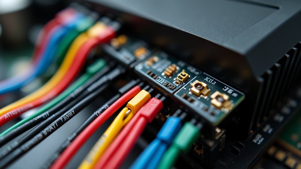
When installing a tracker in your vehicle, proper power supply connections determine whether your device will function reliably over time. You’ll need to connect to the OBD2 port, where the orange pin supplies power to your tracker.
Always start with the ground connection first. Locate the black wire with a white stripe in the OBD2 connector, positioned four slots above the power wire.
Begin by establishing the ground connection. The black/white striped wire sits four slots up from power in your OBD2 connector.
Carefully strip both the tracker’s wires and OBD2 connector wires before making connections. Ensure all connections are properly soldered and individually taped to prevent shorts.
Once connected, route your wiring neatly throughout the vehicle and secure with zip ties. This organized approach not only looks professional but prevents wire interference with vehicle components during future maintenance or servicing.
Wiring the Arduino Controller System
Wiring your Arduino controller system correctly guarantees optimal tracker performance and longevity.
Always begin by connecting the ground wire first to protect the sensitive components from potential damage during setup.
The power wire, identifiable by its orange pin, must be secured to the bottom right corner of the OBD2 connector.
Solder all connections and tape them individually to prevent shorts or disconnections while the device is in operation.
For a clean installation, route your wires behind the headlight switch, which will maintain accessibility for future maintenance or troubleshooting.
Once all connections are in place, verify they’re secure before finalizing the installation.
Position the antenna upright to guarantee ideal signal reception and transmission capabilities.
Installing and Connecting the Motor Driver
To install the motor driver correctly, you’ll need to connect the orange power wire from the OBD2 connector to the driver’s power input and attach the black/white-striped ground wire to complete the circuit.
Prepare your wires by stripping them properly before soldering to guarantee strong electrical connections that won’t fail during operation.
After making all connections, secure the wiring harness with zip ties to the factory harness and verify everything works properly before reassembling your tracker’s components.
Motor Connection Basics
Proper installation of your motor driver requires careful attention to wire connections and polarity. Connect the motor power wires to the appropriate terminals on your driver—red (positive) and black (negative)—to prevent reverse polarity damage.
Never mix these up as it can destroy your components.
For speed and direction control, connect the PWM pins from your microcontroller to the designated control inputs on the motor driver. Confirm you’re using 18-20 AWG wires for small motors to handle current without overheating.
Always connect the motor driver’s ground wire to the common ground of both your power supply and microcontroller. This maintains a stable voltage reference across your system.
Before powering up, double-check that all connections are secure and properly insulated to prevent shorts and potential damage.
Driver Wiring Sequence
When installing your motor driver, the correct wiring sequence is critical for both functionality and safety. Begin by identifying the orange power wire that connects to the bottom right corner of the OBD2 connector. Next, attach the ground wire (black with white stripe) four slots above the power wire—always connect this first to prevent damage.
| Wire Type | Connection Point | Color | Installation Order |
|---|---|---|---|
| Ground | Four slots above power | Black w/white stripe | First |
| Power | Bottom right OBD2 corner | Orange | Second |
| Signal | Varies by model | Various | Third |
| Antenna | Behind instrument cluster | N/A | Last |
Strip all wires before connecting, then wrap and solder each junction securely. Route your wiring harness neatly alongside the factory harness, using zip ties for a clean installation. Position the antenna upward for ideal signal reception.
Testing Circuit Connectivity and Functionality
Once your wiring connections are complete, testing the circuit connectivity and functionality becomes essential to guarantee your tracker will operate reliably. Use a multimeter to check voltage at the OBD2 connector, confirming the orange pin shows proper power output.
Verify the ground connection by testing continuity between the black wire with white stripe and the vehicle chassis. This confirms proper grounding is established. Examine each soldered joint individually to identify any weak connections that might cause intermittent failures.
Conduct a functionality test by connecting your tracker to the OBD2 port. Confirm it powers up and successfully communicates with your vehicle’s systems.
After installation, monitor the tracker’s performance and ascertain the antenna is positioned correctly for peak signal reception. These verification steps will help prevent future connectivity issues.
Weatherproofing Your Wiring Connections
Properly weatherproofing your wiring connections is essential for protecting your tracker against moisture infiltration and temperature fluctuations that can quickly destroy sensitive electronics.
You’ll need to apply heat shrink tubing and silicone sealants at connection points to create watertight seals that maintain signal integrity even in harsh conditions.
These protective measures aren’t just about durability—they’re critical for preventing signal degradation and ensuring your tracker remains reliable regardless of the environment it faces.
Sealing Against Moisture
In harsh outdoor environments, moisture poses one of the greatest threats to your tracker’s electrical system. Preventing water ingress requires multiple layers of protection to guarantee your connections remain reliable over time.
- Apply heat shrink tubing over all soldered joints to create a waterproof barrier that prevents moisture from reaching bare conductors.
- Use silicone sealant around connectors and junction points for additional protection against humidity and direct water exposure.
- Coat exposed wire ends with dielectric grease to repel moisture and prevent corrosion at terminal points.
- Route wiring harnesses strategically to promote water drainage and keep connectors positioned away from areas prone to water accumulation.
Remember to inspect these weatherproofing measures regularly, as environmental exposure can degrade seals over time, compromising your tracker’s electrical integrity.
Temperature Fluctuation Protection
Weatherproofing your wiring connections against temperature fluctuations requires specific materials and techniques beyond basic moisture protection.
Heat-shrink tubing creates an excellent waterproof seal over soldered connections, preventing moisture ingress as temperatures change.
Always verify your connections are securely soldered before applying insulation with electrical tape or heat-shrink. For enhanced protection, use weatherproof connectors specifically designed to withstand extreme temperature variations.
Don’t overlook entry points where wires penetrate housings or devices. Apply silicone sealant around these areas to prevent water and air leaks that could cause temperature-related damage.
Make inspection and maintenance part of your routine. Check all connections regularly for signs of wear or exposure, and promptly replace any compromised connections to maintain peak performance regardless of temperature conditions.
Maintaining Signal Integrity
Signal integrity remains the cornerstone of reliable tracker performance, particularly when environmental factors threaten connection quality.
Weatherproofing your connections protects against moisture and corrosion that can degrade signal transmission over time.
- Apply heat shrink tubing over soldered connections to create a weatherproof seal that prevents moisture infiltration
- Use silicone sealant around wire entry points to block water ingress and extend connection life
- Install waterproof connectors specifically designed for outdoor applications to maintain consistent signal quality
- Route wiring strategically away from windows and undercarriage areas where water exposure is common
Don’t overlook regular inspections of your wiring system.
Check for wear indicators like cracking insulation or corrosion. Reseal compromised connections immediately to prevent signal degradation and guarantee your tracker functions reliably regardless of weather conditions.
Troubleshooting Common Wiring Issues
When wiring issues arise with your tracker, a systematic approach to troubleshooting can save you time and frustration. Start by verifying that the ground wire was connected first during installation, as this prevents potential device damage.
Check that the orange pin is properly connected to the power wire and secured firmly. A loose power connection is often the culprit behind intermittent tracker operation. Confirm the ground wire is positioned exactly four slots above the power wire, maintaining proper wiring integrity.
Inspect your zip ties to guarantee the wiring harness remains secured to the factory harness. Loose connections from movement can cause unpredictable performance issues.
If signal problems persist, verify your antenna is positioned upward for peak reception.
Remember that most tracker issues stem from simple connection problems that you can fix with careful inspection.
Optimizing Tracker Performance Through Proper Wiring
Proper wiring isn’t just about making connections—it’s the foundation of your tracker’s reliability and performance. When installing your tracker, connect the ground wire (black with white stripe) first to the pin four slots above the power connection to prevent damage during setup.
For ideal functionality:
- Connect the power wire to the orange pin at the bottom right corner of the OBD2 connector
- Position the tracker’s antenna facing upward to maximize signal reception
- Route wires behind the headlight switch and secure them to the factory harness with a zip tie
- Hide the tracker behind the instrument cluster for stealth, but guarantee it remains accessible
After installation, always double-check all connections and test the unit to confirm proper operation before finalizing your setup.
Advanced Motor Control Techniques for Precision Tracking
While getting your wiring fundamentals right establishes reliable connectivity, achieving high-precision tracking requires sophisticated motor control strategies.
Implementing PID controllers lets you minimize tracking errors by continuously adjusting motor output based on position differences between setpoint and actual location.
You’ll achieve smoother movements by utilizing high-frequency PWM signals for finer control over motor speed and torque.
Combine multiple sensor inputs through sensor fusion to enhance tracking accuracy with more reliable position data.
Real-time feedback loops greatly improve your tracker’s responsiveness in dynamic environments by constantly adjusting motor commands based on incoming tracking data.
For ultimate precision, incorporate Kalman filtering algorithms to reduce noise and improve position estimates, especially when dealing with environmental interference or sensor limitations.
Frequently Asked Questions
How to Wire a Car Tracker?
To wire a car tracker, connect the orange power wire to the OBD2 connector’s bottom right pin and the black/white ground wire four slots above. Secure with solder, mount on the vent, and manage wiring neatly.
How to Figure Out Which Wire Goes Where?
To figure out which wire goes where, check your tracker’s manual for color coding. You’ll need to identify the power (orange pin) and ground wire (black with white stripe) on the OBD2 connector first.
How to Connect Cable Tracker?
Connect your cable tracker by first attaching the ground wire (black with white stripe) to the OBD2 connector, then the power wire (orange pin). Solder connections, insulate with tape, and mount the tracker using double-sided tape.
How Many Wires Does a GPS Tracker Have?
Most GPS trackers have 4-6 wires. You’ll typically find power (red), ground (black), ignition, and data wires. The exact number varies by model, with advanced trackers offering additional connections for external features.
In Summary
You’ve now mastered the essential wiring connections for your barn door tracker. By properly connecting your motor, controller, and power supply, you’ll achieve accurate celestial tracking for astrophotography. Don’t forget to weatherproof all connections and test thoroughly before your first night session. With these wiring fundamentals in place, you’re ready to capture stunning long-exposure images of the night sky.


Leave a Reply