A threaded rod star tracker (also called a barn door tracker) is a budget-friendly DIY astrophotography device that counteracts Earth’s rotation, preventing star trails in your long-exposure night sky photos. It consists of two wooden boards connected by a hinge, with a threaded rod that moves at precisely 0.2507° per minute when aligned with Polaris. You’ll need wood, a hinge, a motor, and a threaded rod to build this simple yet effective device that can dramatically improve your celestial photography results.
12 Second-Level Headings for “What Is A Threaded Rod Star Tracker?”

Astrophotographers seeking budget-friendly solutions will find the threaded rod star tracker an ingenious device. Also known as a motorized barn door tracker, this DIY tool counteracts Earth’s rotation during long exposure photography, preventing star trails in your images.
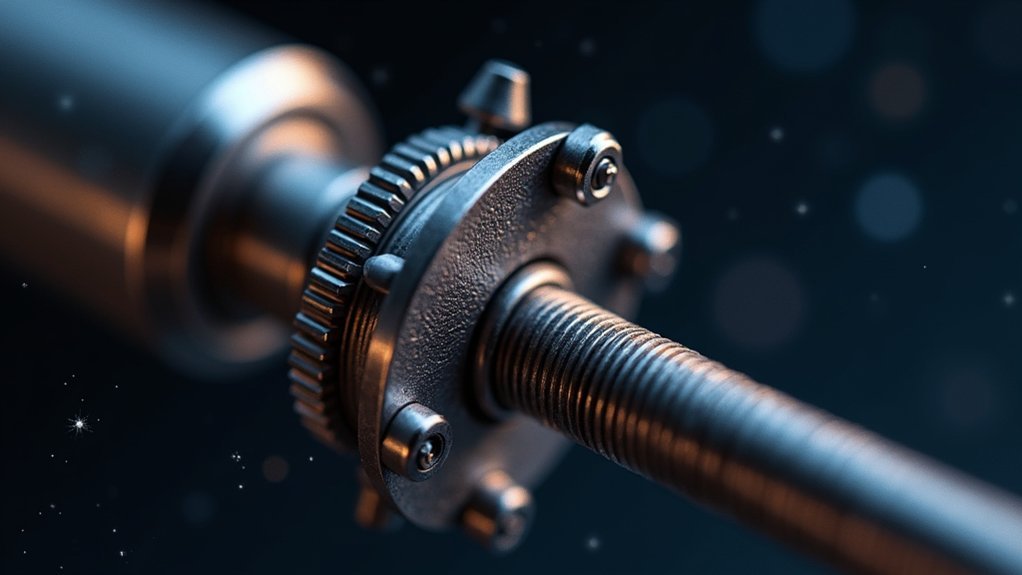
The system works through a simple mechanical principle: a hinge creates a pivoting point, while a motor drives a threaded rod at precisely 0.2507° per minute. This motion matches Earth’s rotation rate, keeping your camera fixed on celestial targets.
A precise motor-driven mechanism that counteracts Earth’s rotation, allowing your camera to follow the stars across the night sky.
What makes these trackers appealing is their accessibility—you can build one using common materials like wood, a hinge, and a 1 rpm synchronous motor.
When properly aligned with Polaris, even a homemade tracker delivers impressive results for astrophotography enthusiasts on a budget.
The Basics of Barn Door Star Tracking
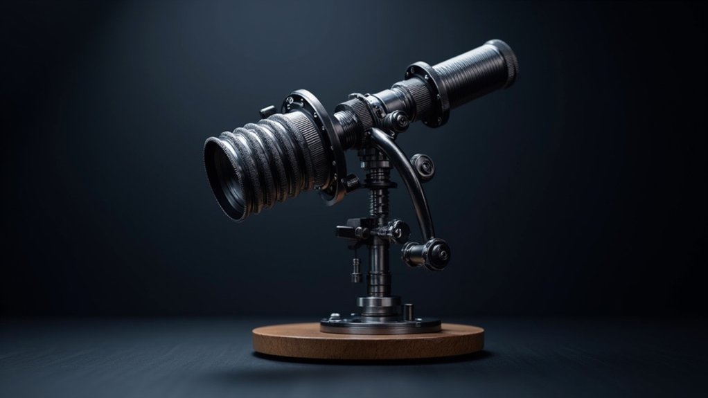
The barn door star tracker represents one of the most elegant and accessible DIY solutions in amateur astronomy. It consists of two wooden boards joined by a hinge, with the bottom board aligned to the North Star and mounted on a tripod. The top board holds your camera and moves via a threaded rod mechanism.
| Component | Function | Adjustment |
|---|---|---|
| Hinge | Pivot point | Aligned with Earth’s axis |
| Threaded rod | Drive mechanism | Rotates at 0.25° per minute |
| Top board | Camera platform | Follows celestial motion |
You’ll find that turning the threaded rod, either manually or with a motor, compensates for Earth’s rotation by gradually opening the hinge. This simple yet effective design eliminates star trails during long exposures, allowing you to capture stunning celestial details without expensive equipment.
Materials and Tools Required for Your DIY Build
Building your own threaded rod star tracker requires just seven essential components, making this project both affordable and accessible.
You’ll need a 500mm length of 22mm × 69mm pine for the main tracker body and 300mm of 22mm × 44mm meranti for the camera platform.
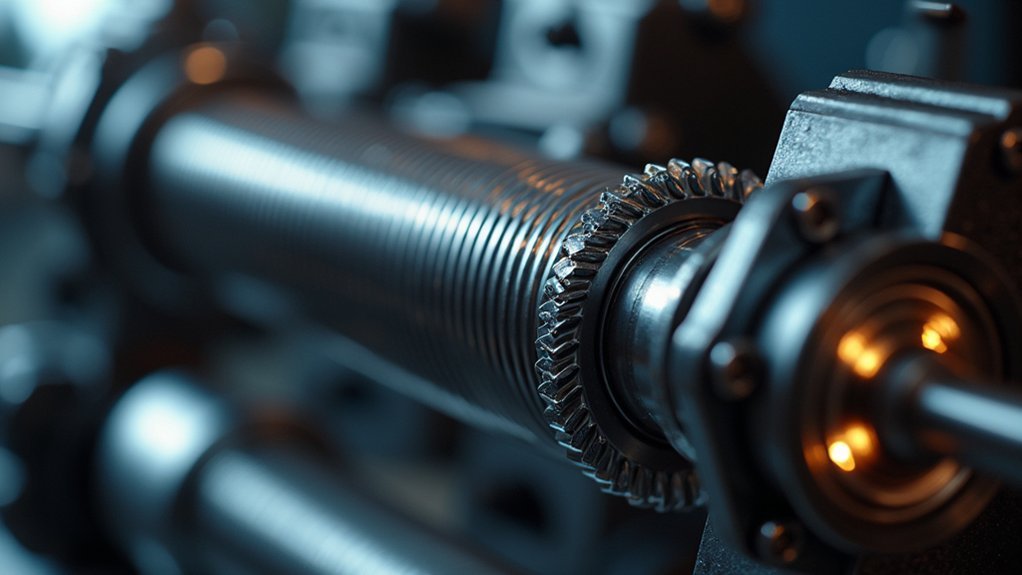
The heart of your system is a 230V AC synchronous motor with a 1 rpm rotation speed that drives the tracking mechanism. An M6 drive rod serves as the curved threaded rod that enables precise celestial tracking.
A precision 230V synchronous motor powering a curved M6 threaded rod creates the perfect celestial tracking system.
Don’t overlook the solid brass hinge—it’s vital for eliminating play and maintaining stability during operation.
Complete your materials list with wood screws for assembly and a sturdy tripod to mount your finished tracker for best star photography results.
Understanding the Mathematics Behind Star Tracking
To build an effective threaded rod star tracker, you’ll need to grasp the angular position calculations that translate Earth’s rotation rate of 0.2507° per minute into your mechanical design.
You’ll also want to understand precession correction methods, which involve compensating for the gradual shift in Earth’s rotational axis through appropriately designed cams or adjustment mechanisms.
Error propagation analysis helps you identify how small inaccuracies in your rod pitch or motor speed might affect tracking precision, allowing you to minimize star trailing in your astrophotography results.
Angular Position Calculations
Mastering the mathematics behind star tracking requires understanding three fundamental calculations. First, you’ll need to determine the Earth’s rotation rate relative to the stars – approximately 15.041° per hour based on the 23 hour, 56 minute sidereal day. Then, calculate the angular tracking rate needed for your camera to follow this motion smoothly.
When designing your threaded rod star tracker, these angular position calculations translate directly to mechanical specifications:
| Measurement | Value | Application |
|---|---|---|
| Sidereal day | 23h 56m 4.0916s | Base rotation period |
| Diurnal motion | 15.041°/hour | Star movement rate |
| Tracking rate | 0.2507°/minute | Camera movement needed |
| Rod length | 228.56mm | For 1mm pitch thread |
These precise calculations guarantee your threaded rod moves your camera at exactly the right speed to match celestial motion.
Precession Correction Methods
While achieving basic star tracking provides beautiful night sky photos, accounting for Earth’s precession brings your astrophotography to professional levels.
Precession correction compensates for the gradual shift in Earth’s rotational axis, which affects star alignment over extended periods.
To implement precession correction in your threaded rod tracker, you’ll need to calculate adjustments based on your latitude and the Earth’s tilt angle. The standard tracking rate of 0.2507° per minute (based on the 23-hour 56-minute sidereal day) requires fine-tuning with a specially designed cam.
When using an M6 threaded rod with 1mm pitch, you can derive precise mathematical equations to adjust your tracker’s rotation.
These calculations guarantee your camera maintains perfect alignment with celestial objects despite precession effects, resulting in sharper star images and more accurate long-exposure photography.
Error Propagation Analysis
Understanding error propagation represents the most vital aspect of designing an effective threaded rod star tracker.
When you calculate the cumulative effects of measurement uncertainties, you’ll find that even minor angular misalignments can greatly impact tracking accuracy over time.
With celestial objects moving at 0.2507° per minute (based on the 23-hour 56-minute sidereal day), your threaded rod must travel precisely 228.56mm when using a 1mm pitch.
The hinge pin alignment becomes particularly vital, as deviations here multiply throughout the system.
Error propagation analysis helps identify how mechanical tolerances affect performance.
Small discrepancies in motor speed or hinge geometry can accumulate rapidly during long exposures.
That’s why the corrective cam design proves invaluable—it compensates for geometric distortions, ensuring your tracker maintains accuracy despite the inevitable small imperfections in the system.
Cutting and Preparing the Wooden Components
Begin by gathering your solid pine and meranti wood pieces for this project. Cut your main tracker body to exactly 500mm from the 22mm x 69mm solid pine, ensuring both ends are perfectly square for proper hinge attachment later.
Carefully select and cut premium pine to precise measurements—the foundation of your DIY tracker’s accuracy and stability.
For the camera mount, cut approximately 300mm from your meranti wood (22mm x 44mm) to create a stable platform for your camera equipment.
Next, drill precision holes in the stationary board to accommodate the M6 threaded rod, which will serve as your drive mechanism. Install an M6 Tee nut to enhance stability and provide secure anchoring.
When selecting your hinge, opt for a solid brass 63mm type with minimal play. This precision will enable smooth tracking movement.
Create parallel sliding mounts for the motor shaft to allow for fine-tuning and proper alignment with the drive rod.
Hinge Selection and Alignment Techniques
Selecting a solid brass hinge with minimal play is critical for your star tracker’s stability, and you’ll need to properly align it on the east side with the hinge pin allowing free movement while maintaining tension.
You should aim the device south and adjust the tilt to match your latitude, using a protractor during setup to guarantee accurate tracking of celestial objects.
Remember to position your motor on the west side for correct rotational direction, which complements the hinge’s orientation for ideal tracking performance.
Key Hinge Considerations
The heart of a successful threaded rod star tracker lies in its hinge, which must be carefully selected and precisely aligned to achieve ideal results.
You’ll need to choose a hinge with minimal play – a solid brass hinge around 63mm works excellently for ensuring stability during long exposures.
When mounting your hinge, secure it firmly between the two boards to allow smooth movement while maintaining precision.
The critical alignment step requires positioning the hinge pin directly toward Polaris, ensuring your tracker follows Earth’s rotation accurately.
Additionally, you’ll need to set the hinge at an angle matching your latitude for proper diurnal motion tracking.
Polar Alignment Methods
Once your hinge is mounted securely, you’ll need to master proper polar alignment for tracking success. Position your hinge at an angle equal to your latitude, ensuring it points toward the polar star (Polaris). This alignment allows your star tracker to rotate in perfect sync with Earth’s rotation, compensating for our planet’s movement.
- Use a protractor to set your hinge at the precise latitude angle
- Align the hinge’s rotation axis directly with Polaris for accurate tracking
- Mount a laser pointer parallel to your hinge for improved pointing precision
- Alternatively, attach a straw alongside the hinge as a simple sighting tool
- Regularly check that your hinge moves smoothly without play or binding
Proper polar alignment transforms your threaded rod tracker from a simple mechanism into a reliable astronomical tool.
Reducing Hinge Play
Because your star tracker’s precision depends heavily on the hinge’s stability, choosing and properly aligning the right hinge becomes critical to your astrophotography success.
Select a solid brass 63mm hinge with minimal play to reduce unwanted movement that could compromise your imaging results.
When installing your hinge, sight towards the south to properly align the hinge pin, ensuring accurate celestial tracking.
Check that the hinge moves smoothly without binding or excessive looseness—this balance greatly improves tracking performance.
Maintain square alignment throughout assembly and periodically verify this alignment during use.
A precision-manufactured hinge reduces the need for constant adjustments, delivering more reliable tracking results.
Remember that even small imperfections in hinge alignment can translate to noticeable errors in your star tracker’s performance over extended exposure times.
Mounting and Configuring the Threaded Rod
Proper mounting of the threaded rod forms the critical foundation of your star tracker’s performance.
You’ll need to secure the rod to enable smooth rotation that precisely matches Earth’s 0.2507° per minute sidereal motion. The rod’s pitch, typically 1mm, determines the motor speed required for accurate tracking.
Earth’s rotation demands precision—a star tracker with 1mm pitch rod translates sidereal motion into perfect astronomical exposures.
- Attach a solid hinge to the main tracker body with minimal play for stability.
- Position the hinge to align with Polaris when operating in the Northern Hemisphere.
- Mount your camera on the 300mm meranti wood platform for ideal balance.
- Verify the threaded rod is perfectly perpendicular to the hinge axis.
- Test the rotation before your first shoot to confirm smooth movement.
This configuration allows your camera to track celestial objects during long exposures without producing star trails in your images.
Motor Selection and Installation Options
When selecting a motor for your threaded rod star tracker, you’ll want a 230V AC synchronous motor running at 1 rpm to precisely match Earth’s rotation.
You’ll need to connect the motor to the drive rod using a coupling nut while ensuring the motor shaft remains parallel to the threaded rod for binding-free operation.
A PWM motor controller will help you fine-tune tracking accuracy based on your camera’s weight, particularly important for achieving sharp long-exposure astrophotography.
Motor Selection Criteria
Selecting the right motor forms the backbone of any successful star tracker build. When choosing your motor, prioritize rotational movement that precisely matches Earth’s rotation rate for ideal tracking during long exposure astrophotography.
- Choose a 230V AC synchronous motor with 1 rpm speed for accurate celestial tracking.
- Make sure your motor can connect to the drive rod using an M6 coupling nut for smooth power transmission.
- Verify the motor rotates clockwise after installation to guarantee proper board closure.
- Consider adding a PWM speed controller to fine-tune tracking based on different lens loads.
- Align your motor carefully with the hinge and threaded rod to eliminate vibrations during operation.
Your motor selection criteria should focus on stability, precise speed control, and proper mechanical integration to achieve sharp, streak-free astro images.
Installation Alignment Techniques
Achieving perfect alignment during motor installation represents the most critical phase of your star tracker build. When mounting your 230V AC synchronous motor, create parallel sliding mounts that allow for fine adjustments to the motor shaft position. Connect the motor to your threaded rod using an M6 coupling nut for precise rotation control.
| Alignment Step | Key Action | Critical Check |
|---|---|---|
| Hinge Setup | Point toward south | Verify with compass |
| Latitude Tilt | Adjust to local angle | Measure with protractor |
| Motor Mount | Create parallel slides | guarantee smooth movement |
| Rod Connection | Secure with M6 coupling | Check for wobble |
| Direction Test | Run clockwise | Confirm boards close properly |
You’ll need to sight the hinge pin southward and tilt it to match your latitude for ideal tracking at 0.2507° per minute, perfectly compensating for Earth’s rotation during astrophotography sessions.
Building an Effective Camera Platform
The heart of your star tracker’s success lies in constructing a robust camera platform that can withstand the demands of long-exposure astrophotography.
Your camera platform must securely support the weight of your equipment while maintaining precise alignment with the threaded rod mechanism.
- Design your platform to support approximately 0.5 kg for ideal tracking performance
- Install a high-quality ball head mount for flexible camera positioning
- Guarantee rigid connection between the platform and the M6 threaded rod (1mm pitch)
- Use lightweight yet sturdy materials to minimize stress on the tracking mechanism
- Create a balanced weight distribution to prevent unwanted movement during exposures
This thoughtful construction will allow your threaded rod to rotate the camera at the required 0.2507° per minute, perfectly counteracting Earth’s rotation and producing crisp, trail-free astrophotographs.
Polar Alignment for Accurate Tracking
With your camera platform firmly constructed, your attention must now turn to polar alignment—the foundation of successful star tracking. This vital process aligns your tracker with Earth’s rotational axis by pointing it at Polaris, the North Star.
Set your tracker’s angle to match your latitude using a protractor and compass. Even minor misalignments can ruin long exposures, turning crisp stars into elongated trails. Confirm the hinge pin is level and properly aligned with Polaris for smooth tracking motion.
Remember to check your polar alignment whenever you change locations or after extended usage periods. This consistent attention to alignment details is what separates amateur results from professional-quality astrophotography.
Proper polar alignment allows your threaded rod tracker to compensate accurately for Earth’s rotation, delivering the sharp celestial images you’re aiming for.
Testing Your Tracker and Troubleshooting
Once you’ve achieved proper polar alignment, you’ll need to thoroughly test your star tracker before attempting any serious astrophotography sessions.
Begin by powering on your motor and verifying it rotates clockwise, which guarantees proper board closure and tracking functionality.
Always verify clockwise motor rotation to ensure proper board closure and maintain accurate tracking performance.
When testing your DIY setup, watch for these common issues:
- Set your tracker to the correct angle using a protractor that matches your geographic latitude
- Ascertain the hinge aligns perfectly with Polaris for accurate celestial tracking
- Monitor for excessive vibration that could blur your images
- Check that the threaded rod is properly lubricated for smooth operation
- Verify all electronic connections are secure and correctly configured
If you encounter tracking problems during testing, troubleshoot by removing unnecessary weight and reinforcing any loose connections in your assembly.
Capturing Your First Deep Sky Images
After completing the testing phase, you’re finally ready to capture breathtaking deep sky images with your threaded rod star tracker.
Begin by aligning your tracker with Polaris, ensuring the threaded rod will rotate your camera at the exact rate of Earth’s movement.
Mount your camera securely to prevent vibrations during long exposure shots. For best results, use these settings: 30+ second exposures, ISO 800, and apertures around f/4.
Your threaded rod mechanism will compensate for Earth’s rotation, allowing stars to appear as crisp points rather than trails.
Capture images in RAW format for maximum post-processing flexibility.
After your session, import your photos into DeepSkyStacker to combine multiple frames, dramatically improving detail and reducing noise in your final astrophotographs.
Frequently Asked Questions
What Is the Purpose of a Star Tracker?
A star tracker compensates for Earth’s rotation during long-exposure photography. You’ll capture celestial objects without star trails, enabling you to collect more light and reveal detailed images of faint astronomical features.
How Do You Use a Star Tracker?
To use a star tracker, you’ll aim its hinge at Polaris, secure your camera in bulb mode, and rotate the handle at specific intervals based on your lens focal length to counteract Earth’s rotation.
What Is the Difference Between a Star Tracker and a Guider?
A star tracker rotates your camera to follow celestial motion, while a guider provides real-time corrections to your telescope. You’ll use trackers for wide-field shots and guiders for precise targeting of specific celestial objects.
How Does a Barn Door Tracker Work?
A barn door tracker works by mimicking Earth’s rotation. You’ll hinge two boards together, align one with Polaris, and use a threaded rod to slowly rotate the camera-mounted board, tracking stars during long exposures.
In Summary
You’ve now learned how to build and use a threaded rod star tracker, also known as a barn door tracker. By making this simple yet effective device, you’ve opened the door to astrophotography without spending thousands on equipment. With practice and patience, you’ll capture stunning deep sky objects that weren’t possible before. Keep refining your technique, and don’t forget to share your celestial images!


Leave a Reply