To assemble a barn door tracker motor, first secure your 1 rpm synchronous motor to the base board using brackets aligned parallel to the M6 threaded rod. Connect the motor to your PWM speed controller, ensuring proper polarity and voltage. Attach the drive rod to the motor coupling, verify clockwise rotation, and test that one complete rotation takes 60 seconds. Align the hinge axis with Polaris for accurate tracking. Follow the detailed steps below for a complete setup that will capture stunning night sky images.
Understanding Barn Door Tracker Mechanics
While astrophotography requires specialized equipment for capturing celestial objects, a barn door tracker offers an affordable DIY solution. At its core, this device operates as an isosceles triangle, with a stationary base board and a pivoting drive arm that gradually closes to track the night sky’s motion.
The key components include a central hinge where the arm pivots and a drive rod that controls the closing rate. As the drive arm swings shut at approximately three inches per hour, it maintains alignment with celestial bodies, preventing star trails in long exposures.
The heart of a barn door tracker lies in its precise motion—a slowly closing arm that follows the stars’ path across our night sky.
The drive rod, typically a quarter-twenty threaded rod rotating at one revolution per minute, must maintain proper geometric relationship with the hinge to guarantee accurate tracking.
For ideal results, you’ll need to align your tracker precisely toward Polaris before beginning your imaging session.
Required Components and Materials
When building your barn door tracker motor, you’ll need several essential components including a 230V AC synchronous motor (1 rpm), an M6 threaded rod, and a solid brass hinge with minimal play.
Quality materials matter greatly—choose sturdy pine for your base board, reliable wood screws, and approximately 300mm of meranti (22mm x 44mm) for the camera mount.
You’ll also require basic assembly tools such as a drill with various bits, a screwdriver set, measuring tools, and potentially a power supply like a 12V DC source or PWM motor speed controller.
Essential Motor Components
Building a successful barn door tracker requires several critical components working in harmony.
At the heart of your system is a 230V AC synchronous motor running at 1 rpm, which provides the precise movement needed for tracking celestial objects. This motor connects to your drive mechanism via an M6 threaded rod with 1mm pitch, enabling accurate tracking as your camera mount follows the night sky.
You’ll need a PWM motor speed controller to fine-tune the tracking speed based on your camera and lens weight.
Don’t overlook the importance of a solid brass hinge with minimal play, as this guarantees smooth movement during operation.
Complete your setup with a sturdy baseboard, appropriate gears for the correct ratio, and a ball head mount to securely position your camera equipment.
Selecting Quality Materials
Three essential material choices will determine the quality and performance of your barn door tracker.
First, select a solid brass hinge (approximately 63mm) to guarantee the tracker maintains precise alignment with minimal play during operation.
For the tracker body, choose pine wood cut to 500mm length with 22mm x 69mm dimensions. This provides the sturdy structure needed to support your equipment while maintaining relatively light weight.
The heart of your barn door tracker is a 230V AC synchronous motor running at 1 rpm, which drives an M6 threaded rod with the correct pitch to match celestial movement speeds.
This combination creates the smooth, consistent tracking vital for long-exposure astrophotography.
Finally, mount your assembly on a robust tripod that offers the stability required for vibration-free operation under various conditions.
Assembly Tools Needed
Successful assembly of your barn door tracker requires specific tools beyond the core components already mentioned. You’ll need a drill with various bits for creating pilot holes in the pine boards and mounting holes for your camera attachment.
A screwdriver set is essential for securing the wood screws that hold the tracker body together. For working with the M6 threaded rod, gather an adjustable wrench and pliers to properly secure the Tee nuts and create the drive mechanism.
A ruler and square will guarantee your measurements are precise, particularly when aligning the hinge with the 500mm pine boards. Don’t forget a level to confirm your tracker maintains proper orientation when mounted to your tripod.
Finally, sandpaper will help smooth rough edges that might interfere with the tracker’s smooth operation.
Motor Selection and Specifications
Selecting the appropriate motor serves as the cornerstone of a functional barn door tracker. For ideal performance, you’ll want to choose a 230V AC synchronous motor that operates at 1 rpm. This specification guarantees precise rotation needed for accurate celestial tracking.
Your motor should include a coupling compatible with an M6 drive rod, which transmits the rotational movement to your tracking system. Once you’ve installed the motor, check its rotation direction immediately after powering on to verify proper functionality.
Always verify motor rotation direction after installation to ensure proper transmission of movement through the M6 drive rod coupling.
For flexibility with different lens weights, consider adding a PWM motor speed controller. This allows you to fine-tune the rotation speed for perfect tracking results.
Remember to mount your motor securely and align it properly with other components to prevent tracking errors during operation.
Mounting Hardware Preparation

You’ll need to carefully align your motor brackets parallel to the threaded rod to guarantee smooth operation of your barn door tracker.
Select high-quality mounting hardware including M6 Tee nuts and wood screws as mentioned in the specifications to securely fasten components to the pine wood base.
When positioning brackets, use a small machinist’s square to verify perpendicular alignment with the hinge axis, which prevents binding during the tracking motion.
Bracket Alignment Techniques
Proper alignment of your mounting brackets forms the cornerstone of a functional barn door tracker. When mounting the hinge, position it precisely at the correct pivot point on your base board. Use a protractor to verify the hinge angle matches your latitude for ideal celestial tracking.
Improper alignment will result in tracking errors and compromised performance.
Ensure the camera platform’s sliding mount runs parallel to the drive screw to maintain consistent alignment during operation. Before final assembly, check that your base board remains perfectly level using a spirit level—horizontal positioning is essential for accurate object tracking.
Test your alignment by manually rotating the drive arm and confirming smooth engagement with the drive screw. This preliminary check prevents binding issues that could damage your motor or cause tracking inaccuracies.
Hardware Selection Guide
With your brackets properly aligned, now let’s focus on the hardware that will bring your barn door tracker to life.
Select a solid 63mm brass hinge with minimal play to guarantee smooth operation and stability for your tracker.
For the main body, use 500mm long pine (22mm x 69mm) as your foundation. This sturdy material provides the robust base needed for precise tracking.
The camera mount requires approximately 300mm of 22mm x 44mm meranti to securely support your equipment during astrophotography sessions.
Choose an M6 threaded rod for your drive mechanism, assuring compatibility with your motor for precise adjustments.
Complete your assembly with wood screws that fit securely into the construction, providing the necessary strength and durability for your tracker’s components.
Circuit Assembly and Wiring
The electrical heart of your barn door tracker lies in its circuit connections. Begin by connecting the 12V DC power input to your project box, ensuring you’ve matched the voltage requirements of your stepper motor.
Next, wire your stepper motor to the motor driver, carefully observing polarity markings to guarantee correct rotation direction. This connection is critical for proper tracking movement across the night sky.
Incorporate a PWM speed controller into your circuit for precise adjustment of the tracking rate. This fine-tuning capability will greatly enhance your astrophotography results.
Don’t forget to implement the kill-switch mechanism using an old padlock key as your emergency stop. This safety feature prevents potential damage to your motor during operation.
Before final assembly, perform power-on tests to verify all connections are secure and functioning correctly.
Drive Mechanism Installation
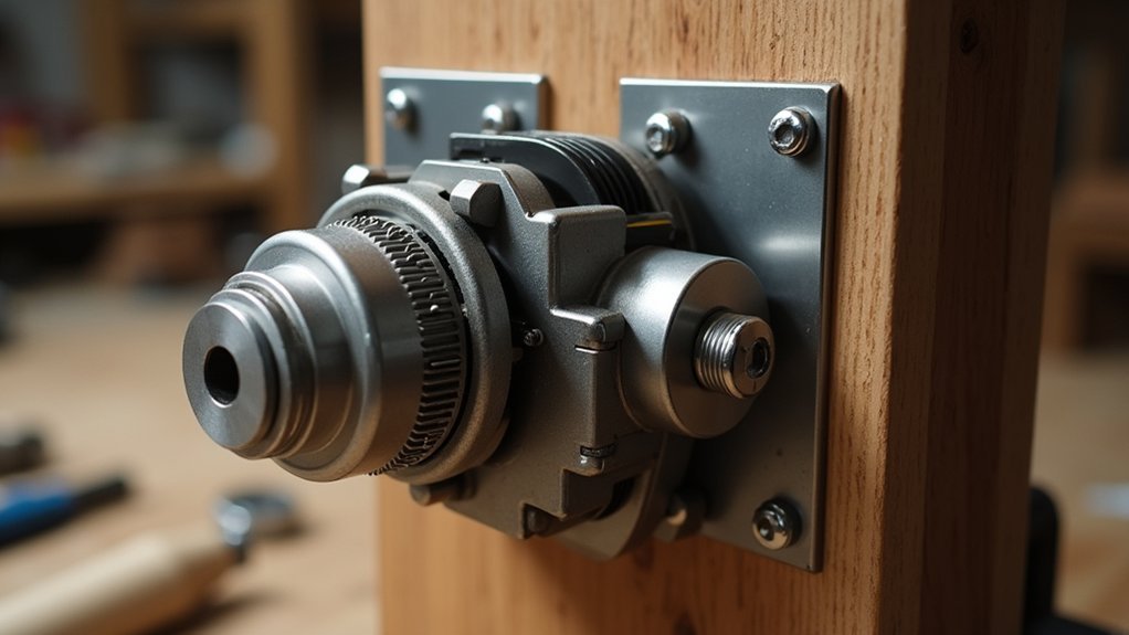
Installing the drive mechanism requires precision and careful alignment to guarantee smooth tracking performance. The drive mechanism forms the heart of your barn door tracker, converting motor rotation into the precise movement needed for astrophotography.
- Secure the drive arm to the base board with the tracker’s hinge, ensuring it swings freely without any resistance that could affect tracking accuracy.
- Attach the quarter-twenty drive screw to the drive arm, maintaining parallel alignment with the arm’s hinge while allowing it to pivot naturally with the arm’s movement.
- Measure and mark the critical distances: r (hinge to drive screw), b (to sliding contact), and c (from arm hinge to camera platform hinge) to establish proper geometric relationships.
Once properly installed, your drive mechanism will rotate at one revolution per minute, providing the ideal three-inch hourly travel rate.
Speed Control System Setup
Now that your drive mechanism is properly positioned, you’ll need to configure the speed control system—the brain that regulates your tracker’s movement.
Mount the PWM motor speed control unit securely on the base board, ensuring it’s accessible for adjustments during operation.
Connect your speed controller to a 12V DC power supply, then attach the motor wires with correct polarity. The controller should allow you to fine-tune the rotation to approximately 1 RPM—ideal for tracking celestial objects.
Install the kill-switch using an old padlock key as an emergency stop option. This safety feature prevents potential damage during unexpected situations.
Test your setup by adjusting the speed until one complete revolution takes exactly 60 seconds. When properly calibrated, the red dot indicator should move smoothly, ensuring minimal star trailing during long exposure astrophotography.
Testing and Calibration Procedures
Three essential tests must be performed before your barn door tracker can reliably capture the night sky. After assembly, you’ll need to verify tracking accuracy to minimize tangent error and guarantee your photographs capture round, crisp stars.
- Conduct initial test exposures (around 60 seconds) to assess star trailing and adjust motor speed accordingly.
- Align your red dot finder with the North Celestial Pole after pointing at the polar region for precise object tracking.
- Perform graduated exposure tests (two and four minutes) to evaluate tracking performance under different conditions.
Document all adjustments you make during calibration. Target a rotation speed of approximately 62 seconds for best results.
Regular testing will help identify misalignment issues early, preventing frustration during actual astrophotography sessions and guaranteeing your barn door tracker performs reliably night after night.
Alignment and Field Operation Tips
Once your barn door tracker is assembled, proper alignment becomes the critical factor determining your astrophotography success. Point the hinge axis directly at Polaris, the polar star, to guarantee accurate celestial tracking. Use a compass and protractor to set the correct hinge angle based on your latitude.
Before tracking begins, power on the motor to verify it rotates clockwise, which guarantees proper board closure. Adjust the PWM motor speed control until one complete rotation takes approximately 60 seconds, matching Earth’s 15-degree rotational movement.
After initial alignment, regularly check that your red dot finder remains precisely aligned with the North Celestial Pole throughout your session. This continuous verification helps maintain tracking accuracy and ultimately results in sharper, streak-free astrophotographs.
Frequently Asked Questions
How Long Can a Barn Door Tracker Run on Batteries?
Your barn door tracker’s battery life depends on your battery type. You’ll get a few hours from standard batteries, but rechargeable or high-capacity ones can last all night for extended astrophotography sessions.
Can I Use a Barn Door Tracker in the Southern Hemisphere?
Yes, you can use a barn door tracker in the southern hemisphere. You’ll just need to rotate it 180 degrees and align it with the south celestial pole instead of the north pole.
What’s the Maximum Weight a DIY Tracker Can Support?
Your DIY tracker can typically support 5-10 pounds, depending on your build quality and materials. You’ll want to reinforce it with sturdy components if you’re mounting heavier equipment like telescopes or long lenses.
How Accurate Is a Homemade Barn Door Tracker?
A homemade barn door tracker can be surprisingly accurate if you’re careful with construction. You’ll achieve 10-30 minute exposures with good results, though accuracy depends on your craftsmanship and motor control precision.
Can I Adapt Commercial Camera Mounts for My Tracker?
Yes, you can adapt commercial camera mounts for your barn door tracker. They’ll provide stable support and easy adjustments. Look for mounts with standard 1/4″ threads that can handle your camera’s weight and tracking movements.
In Summary
You’ve now built your own motorized barn door tracker! By carefully assembling the motor, drive mechanism, and control system, you’ve created a reliable tool for astrophotography. Remember to test thoroughly and make calibration adjustments as needed. With practice, you’ll capture stunning long-exposure night sky images without star trails. Enjoy your new DIY astronomy equipment under the stars!




Leave a Reply